Semi-Automated Micro Assembly for Rapid Prototyping of a One DOF Surgical Wrist
Ranjana Sahai, Jusuk Lee, and Ronald S. Fearing
{rsahai, ronf}@eecs.berkeley.edu
Department of EECS, University of California, Berkeley, CA 94720. USA
Abstract
We have developed new methods for the automated assem- bly of prototype structures and we illustrate them with the construction of a simple one DOF 5mm surgical wrist em- ploying polyester flexures instead of revolute joints. The first step in the structural assembly involves the construc- tion of hollow stainless steel triangular beams that are used for the rigid elements of the structure. It includes the development of a folding fixture to bend stainless steel sheets and the determination of a folding angle sequence by static analysis using a compliant mechanism model. The semi-automatic process of using a millirobot (Ortho- tweezers) to manipulate and assemble the beams and at- tach the flexures is described in detail. The paper ends with a description of the procedure used to design the wrist.
1 Introduction
This paper describes a semi-automated procedure for rapid prototyping of millimeter-scale robotic structures and demonstrates it by building a prototype for a one DOF sur- gical wrist. The long-term goal of this work is to fully au- tomate the fabrication of such structures. This envisioned automated assembly would include the construction of the structure (the body of the robot) and the attachment of ac- tuators, sensors, and any necessary wiring. Because the techniques in the assembly of structures these sizes are largely undeveloped, this goal encompasses a considerable amount of uncharted territory. Thus, as a first step, the cur- rent work focuses on automating the construction of the 3-D structure. More specifically, it focuses on automating or creating fixtures for those tasks that are most difficult to perform by hand (for example, the manipulation and pre- cise positioning of the micro parts). The aim is to develop efficient, reliable, yet flexible fabrication techniques. The proposed methods will then constitute part of a minimal set of robust primitives that can be eventually combined to make a fully automated desktop assembly process for mil- lirobots.
The basic materials chosen to construct these prototype structures are hollow triangular stainless steel beams for the rigid elements and polyester for the flexible elements. During the prototyping stage, where many designs will be tested and discarded, the ready availability and low cost of these materials make them a desirable combination. The rigid elements, made from folding 12.5?m-thick stainless steel sheets, are strong yet lightweight and the polyester flexures are able to withstand large deflections and fatigue cycles for a relatively short size. Although a monolithic structure is ideal from the assembly viewpoint, it is difficult to find a single material with desirable mechanical proper- ties for both the rigid and flexible parts. Furthermore, the particular combination chosen here has been successfully used in prototyping millirobots as demonstrated by the Me- chanical Flying Insect project [1]. In that case, however, the structures had to be made painstakingly by hand.
The present work extends previous work done at UC Berkeley in the area of microassembly. Shimada et al. [2] describe the development of the Ortho-tweezers used in this work for manipulating tiny blocks and the folding process (done by hand) for the stainless steel beams and provide references to previous work in this area. Thomp- son and Fearing [3] detail the addition of a user interface and software primitives using force feedback to the Ortho- tweezers which made the picking and placing of small han- dling blocks possible automatically.
Figure 1 shows a block diagram of the assembly process from a flat sheet to the final 3-D structure and the current status of automation of each step. The present work de- scribes the efforts made towards the automation of the con- struction of the triangular beams and the assembly of the beams and flexures into a 2-D assembly. Specifically, in the section on beam construction, we detail the construction of a folding fixture to bend the thin stainless steel sheets and a theoretical analysis done to determine the set of folding angles. In the assembly section, we describe the devel- opment of interchangeable pallets where handling blocks are attached to the objects to be manipulated and then the handling block and object combination is transported to its desired position.
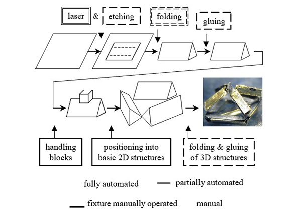
Figure 1: 3-D Structure Assembly Process
The present paper illustrates this procedure through the construction of a prototype for a one DOF wrist for minimally invasive surgery (MIS). These surgical proce- dures require the development of innovative and dexter- ous millimeter-scale instruments. Although conventional designs involving miniature machine parts have been pro- posed (see [4] for example), such mechanisms are difficult to manufacture and assemble and are no longer cost effec- tive beyond a certain level of miniaturization. In addition, rotary and sliding joints used in conventional mechanisms involve surface contact causing unacceptable high friction and wear rates. Compliant mechanisms, in which flex- ures or flexural hinges replace the conventional revolute joints, are capable of overcoming these disadvantages and are therefore highly suited for this application. For these reasons, we have chosen to demonstrate our current semi- automated rapid prototyping assembly process by build- ing a one DOF wrist for use in MIS instruments. Figure 2 shows a SolidWorks model of the proposed wrist. The present design has been kept simple to illustrate the assem- bly process, but the same procedure can be applied to more complicated structures as well.
The details of the triangular beam construction and the assembly process as well as the design process used to choose the parameters of the wrist fabricated are given in the sections below.
2 Triangular Beam Construction
As mentioned previously, we formed the triangular beams from folding pre-cut and pre-scored 12.5?m-thick stainless steel sheets. The folding process, although slower than stamping, provides bending that is more amenable to small, thin sheets. It also allows for greater flexibility in the re- sulting cross-sectional shape of the beams. The stainless steel sheets were pre-cut and pre-scored using the Micro- laze laser micromachining station as described in [2]. The process included pre-coating a small stainless steel piece (approximately 45mm 60mm) with polyimide (HD Mi- crosystems, PI2525), blasting the polyimide with the laser, and etching to produce the cut and score lines. The fixture that we developed for producing the folds in the stainless steel sheets is shown in Figure 3 and consists of three ba- sic parts: (1) the mechanism for bending the sheet, (2) the base on which the stainless steel sheet is placed, and (3) the clamp that holds the steel in place and that also serves as an edge against which the sheet is folded.
-
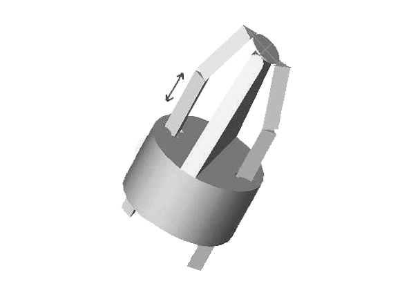
Figure 2: SolidWorks model of the Proposed 1 DOF Wrist
-
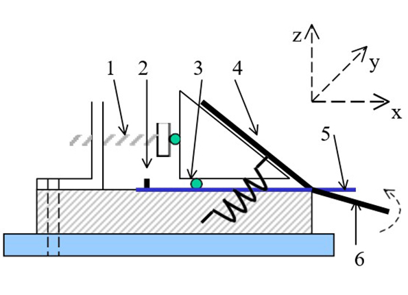
Figure 3: Folding mechanism: (1)clamp-position adjust- ment screw, (2)alignment pin, (3)clamp point contact, (4)upper razor blade, (5)stainless steel sheet, (6)rotating razor blade
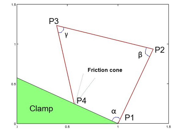
Figure 4: Typical triangular beam folding configuration
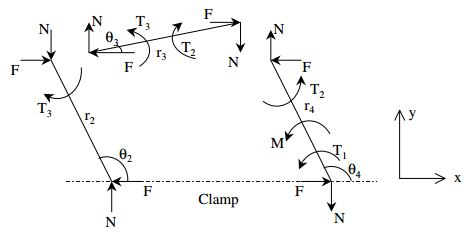
Figure 5: Free body diagram based on a pseudo-rigid com- pliant mechanism model
In order to reduce the springback (for a description of the factors that affect the springback and an approximate way to calculate it, see [2]), an automated folding fixture must provide an almost pure bending moment and minimize the length over which the bending takes place. The folding mechanism pictured in Figure 3 has been designed with this aim in mind. A razor blade attached to the clamp ap- plies a line force along the bend line, and a rotating razor blade underneath the steel provides the bending moment. The rotating razor blade is attached to the base structure using simple flexures made of tape. The base provides a hard and flat surface on which to lay the stainless steel piece. The base in the present fixture was molded out of polyurethane with a 200?m-thick steel piece glued to the area beneath the clamp. It incorporates two alignment pins to ensure accurate placement of the stainless steel sheet each time a fold is made.
The clamp is perhaps the most critical part of the folding fixture. It must be easy to lift up and place accurately in alignment with the bend line on the stainless steel piece be- ing folded. The clamp’s design follows the exact constraint design principles as described in Blanding [5] to avoid over-constraint problems that lead to either loosely fitting or binding parts that are contrary to precise placement. In this case, the clamp uses the exact constraint method of a contact point coupled with a nesting force (provided by tension springs). This method is ideal for parts that are frequently removed and replaced but need to be precisely positioned [5]. In practical use, the clamp is lifted and a pre-cut and pre-scored stainless steel piece is placed on the alignment pins. The clamp is then put down, the springs are put in place to hold it down, and adjustments (using two screws with ball bearings on their tips) are made so that the clamp edge lines up with the steel bend line. Finally, the bottom razor blade is rotated to complete the bend. This process is repeated for all of the bends.
The triangular configuration considered here requires three sequential bends. The folding process in this case consists of bending the sheet metal sequentially at P3, P2, and P1 (Figure 4) until the bent piece just touches the clamp sur- face at P4. Further rotation of P1P2 by applying an in- creasing moment causes the structure to flex somewhat and change its angular configuration. Initially, friction prevents the motion of the end P4 along the surface of the clamp, but at some value of the applied moment, the motion would im- pend. To determine the conditions under which the edge P4 will always move down (rather than up, as was observed in some initial trials) the clamp surface, we need to carry out a static analysis. It is not sufficient to simply choose the angles so that the sheet is physically angled downward at P4; whether the impending motion is up or down depends on the direction of the reactive force at P4. All possible re- sultant reactions must lie within a cone with apex at P4 and vertical semi-angle tan-1 ? (the cone of friction, see Figure 4). For impending motion up or down, the reactive force must lie on the right or left edge of the cone respectively.
We received inspiration from Lu and Akella [6] to model each line shown in Figure 4 as a robotic link. The static analysis presented here is based on the pseudo-rigid com- pliant mechanism model [7]. In this model, the compliant structure of Figure 4 is replaced by a four bar mechanism with rigid links and torsional springs placed at the joints. In the free-body diagrams of Figure 5 based on this model, the T s represent the reactive torques due to the torsional springs. It is easy to verify (by writing the force equilib- rium equations) that the magnitudes of the x-components of the reaction forces at each joint are the same; and the same is true for the y-components as well. These com- ponents along and perpendicular to the clamp surface are designated as F and N respectively in Figure 5; at P4 these represent the friction and normal forces. M is the applied moment.
The torques T1, T2, and T3 depend on the equivalent spring stiffness k and the change in joint angle. The initial values of joint angles ?, ? , and ? (see Figure 4) are determined from the configuration in which P4 just touches the clamp surface. Representing the initial values by the subscript 0, the spring torques are given by
T1 = k(? - ?0); T2 = k(? - ?0); T3 = k(? - ?0)
At the point of impending motion, the friction force reaches its maximum value ?N where ? is the coefficient of friction. The experimentally determined value of 0.2 for ? will be used in the subsequent calculations.
It is convenient to represent the governing equations in a non-dimensional form. The following transformations will be used:
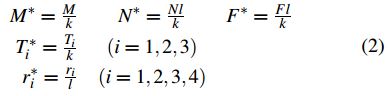
Here, the starred quantities are non-dimensional and l rep- resents a scaling length. The link lengths r2, r3, and r4 (see Figure 5) are constant and assumed equal to the scal- ing length l. The variable distance P1P4 is designated as r1. The angles ?i are shown on Figure 5 and are related to the joint angles by simple geometrical relationships. The non-dimensional governing equations are as follows:
The asterisks in the above equations have been dropped for ease of writing, and all quantities are henceforth presumed to be non-dimensional. Equations (3) and (4) arise from geometrical conditions, and Equations (5), (6), and (7) are moment equations written for each of the free body dia- grams of Figure 5. This system of nonlinear equations can be solved by a variety of numerical procedures; the method chosen here employs the MATLAB function fsolve.
For the solution to have a physical meaning, certain con- straints must be satisfied. The normal force should be pos- itive to ensure physical contact at P4. In addition, ?2 must not exceed 180 degrees. Since the direction of the friction force, (see Figure 5) was chosen so as to indicate impend- ing motion down the clamp, a negative value of the friction force would indicate the undesirable situation of impend- ing motion in the upward direction. Out of the feasible set of angle sequences, we use values ? = 89, ? = 101, and ? = 60 degrees in our work. Although currently the folding mechanism is manipulated by hand, the aim is to fully automate it. Thus it is crucial to know a set of angles that work consistently to obtain a triangular cross section (rather than an open sheet) as a finished product.
Once the triangle has been pre-bent into shape, glue is ap- plied with a needle applicator. Then a fixture with 1mm equilateral triangle channel cut into it is passed repeatedly over the triangle to hold it in place while the glue dries. The fixture is kept in motion with small back and forth move- ments to prevent any glue from attaching the triangle to the fixture (See Figure 6).
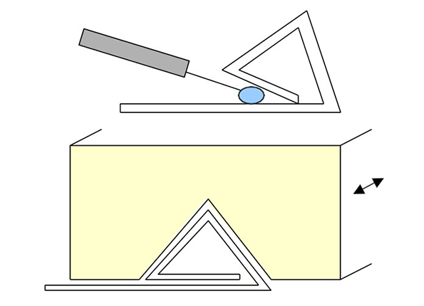
Figure 6: Process used to glue the beams in place
3 The 3-D Assembly Process
Our efforts toward the automatic assembly of these beams into 3-D structures involved the use of the Ortho-tweezers (see Figure 7(a)). Details of this system can be found in [2]. As demonstrated in [2] and [3], the Ortho-tweezers reliably grasp and manipulate blocks. The system’s ca- pabilities have been extended to manipulating objects of other shapes and sizes by first attaching a handling block to the object, and then using the Ortho-tweezers to move the block and object combination by grasping and moving the attached block. The handling block is attached to the object using low melting-point wax so that it can be eas- ily removed after the object has been put into position. A successful demonstration of this method for moving strain gages may be found in [3]. The use of handling blocks allows the system to move objects whose high aspect ra- tio or fragility would preclude them from being handled by conventional tweezers. Thus in our assembly process, the first step is to create a pallet of blocks, wax glue, and the objects that need to be assembled. The Ortho-tweezers are then used to attach the blocks to the objects, thus creat- ing a second interchangeable pallet consisting of the blocks and objects attached together (see Figure 7(b)). In the case where the objects that need to be manipulated are all the same, this step can be done ahead of time and the pallet with block and object combinations can be stored for future use.
For the beam assembly process, the beams are stored in V- grooves at certain definite angles (e.g. 0, 45, 60, 90, or 120 degrees). These V-grooves are of the same shape as those used in the gluing process during the triangular beam con- struction. In the fully automated scheme, these same chan- nels can be used. They would simply be flipped over with the triangular beams inside and slid into place in the pallet. A pallet is constructed with the blocks, spin-coated wax (15?m-thick), V-grooves with the triangular beams, and a rubber mold with V-grooves in a 2-D pattern (a flattened version of the desired 3-D structure). We constructed the V-grooves in the 2-D pattern using a 3-D printing machine (3D Systems ThermoJet machine). A semi-automated pro- cess then begins where the user identifies the position of the block, wax, beam, and target location. Then an auto- mated process begins where the block is grasped, dipped in wax, and attached to the beam (see Figure 8(a)). Then the block and beam combination is picked up (see Figure 8(b)) and placed in the appropriate V-groove in the rubber mold of the 2-D pattern (see Figure 8(c)). This step would be repeated as necessary.
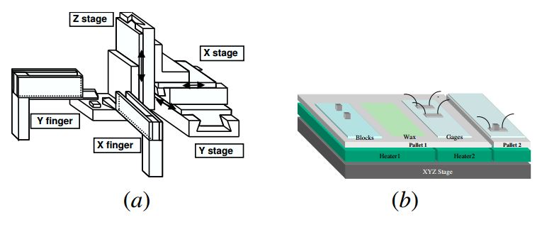
Figure 7: Ortho-tweezers and sample pallet (a) Ortho- tweezer configuration (b) sample pallet showing the attach- ment of handling blocks to strain gages.
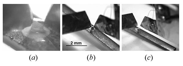
Figure 8: Beam assembly: (a) handling block attached to the beam (b) block and beam being raised from the V- groove (c) beam inserted in V-groove of the 2-D pattern
For the construction of the surgical wrist, another pallet was constructed with polyester strips and a 2-D faceplate (laser-cut from 12.5?m-thick stainless steel in again a flat- tened version of the desired 3-D structure) replacing the V-grooves and the 2-D mold. A thin layer of UV-cure glue was placed on top of the 2-D faceplate. Then a similar process as described for manipulating the beams is per- formed to place the polyester strip (16mm 1mm) on the 2- D faceplate (see Figure 9). Exposure to UV light seals the polyester strips in place. The flexures are created from the polyester strip by the gaps in the stainless steel faceplate below it. Note that in both pallets, the blocks, polyester strips, and the 2-D faceplate are kept on top of Gel-Pak to counteract the sticking force of the parts to the tweezers. (See http://www.gelpak.com for information on Gel-Pak.)
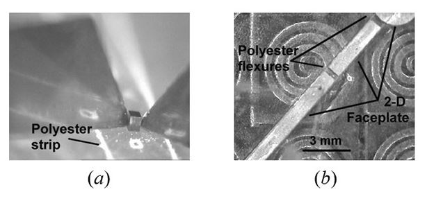
Figure 9: Attaching the flexures: (a) block and polyester strip being transported (b) strip being put in its place on the 2-D faceplate
Tests of the method described above revealed that it could be successfully performed with the user operating the tweezers through the user interface. However, in the auto- mated procedure, user intervention was sometimes needed at the lifting of the block and object combination and at the final placement of the object. Work is currently being done to make this process more reliably performed without user intervention.
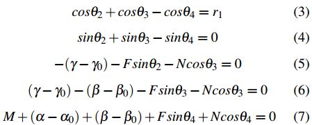
As a final step, the faceplate with the flexure attached is taken and glued on top of the beams in the 2-D mold, removed from the mold, and assembled into the final 3- D structure. As the parts being manipulated here are no longer very small, this step is performed by hand. Fig- ure 10 shows the final results. The structure that holds the wrist in place was constructed from polyurethane from a mold fabricated using the ThermoJet machine.
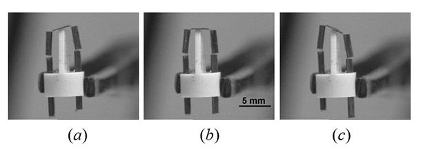
Figure 10: Wrist prototype shown in different configura- tions (a) tilted to the left (b) center position (c) tilted to the right
Finally, it should be noted that the above procedure is eas- ily tailored to make other types of 3-D structures. A similar procedure can also be used to attach strain gages to a struc- ture. Further details of the strain gage attachment can be found in [3] and [8].
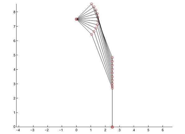
Figure 11: Wrist configurations for platform orientations ranging from -45 to +45 degrees in 10 degree increments
4 Wrist Design
This section presents the design process used to determine the parameters for the wrist whose assembly process is described above. Figure 2 shows a schematic of the planar wrist. The two actuator links manipulate the upper plat- form. The support in the middle provides stability to the platform and takes up some of the load that would other- wise be carried by the two legs. The legs are connected to the upper platform and the actuator links by flexure joints and are both 4mm long.
The kinematics and force analysis of the simple mecha- nism is relatively straightforward. Figure 11 shows the wrist configurations for platform orientations ranging from 45 to +45 degrees. From this geometric study, we de- termined that the maximum angle that the flexures have to bend through is 90 deg. Similar calculations showed that the required stroke length for the actuators is approximately 2.5mm. Based on an applied torque (as estimated by [9]) of 2.2N cm, the calculated value of the actuator force is 18N.
The stiffness of the flexure may be estimated from elemen- tary beam theory as EI/d, where E is the Young’s mod- ulus, I is the cross-sectional moment of inertia, and d is the pivot length. The quantities that need to be specified to calculate the stiffnesses are the width (b), the thickness (h), and the length (d). It is note worthy that the above relation- ship is accurate even when large deflections are involved. For optimum performance, the flexure stiffness should be as small as possible. The stiffness can be reduced by de- creasing E and I (since I is proportional to h3, an effective way to reduce I is to reduce the flexure thickness) or by increasing the length d. The last option is not a desirable one since a long flexure may buckle easily.
For a simple (beam-type) flexure, the appropriate stiff- ness relations can be found in any strength of materi- als book and are given by equations (12-16) of Goldfarb and Speich [10]. The quantities that should be consid- ered when designing simple beam flexures include the ax- ial stiffness (Ebh/d), the transverse or revolute stiffness (Ebh3/12d), and the ratio of axial to transverse stiffness (12/h2). Ideally, the last quantity should be as large as pos- sible. The maximum rotation that a conventional flexure can go through before yielding is also an important param- eter and is given by ?max = 2d?y/Eh. This last relationship can be easily derived from the formula for maximum bend- ing stresses in a beam subjected to pure bending. Here ?y represents the yield stress of the flexure material. As stated earlier, an important additional consideration in flexure de- sign is the buckling of the flexure. Modeling the flexure as a link that is fixed at one end and free on the other, the criti- cal strain as determined from the standard column buckling relationships is given by ( s )crit = p2 ( h )2. Also the minimum length of the flexure for a given angle of rotation and thickness is d (equation 3 from Reference [11]).
It is clear from the above relationships that the material properties play an important part in flexure design. Ideally, the quantity ?y/E should be as large as possible. The met- als (?y/E = .004 for stainless steel) are therefore poor can- didates for flexures. We choose polyester because of its rel- atively high ?y/E value (.06) and superior adhesion prop- erties. Based on the above calculations, we chose 12?m- thick polyester, 1mm wide, and .25mm long. Its properties for some of the quantities discussed above is shown in Ta- ble 1. The platform legs can withstand a buckling load of up to 50N.
Although a variety of actuation methods are possible, we propose to use SMA actuators because of their small size. The required dimensions of the actuators in the present design can be calculated easily by using the relationships given by Waram [12]. The diameter of the actuator wire is given by D = (4F/?? )1/2 and the length is equal to L = stroke/(?1 ?). Here F is the actuator force, ? is the design stress, and ?1 and ? are the high and low strain values. Using a conservative estimate of 25N for the actu- ator force and the stroke length of 4mm (2.5mm actual) we need to use actuator wires 400?m in diameter and 80mm in length. We used ? = 140MPa (to ensure good cycle life) and ?1 = 0.55% and ? = 0.02%.
| kaxial / ktransverse | kmax | Pcrit | dmin |
|---|---|---|---|
| 83, 333(1/mm2) | 143deg | 6.5mN | .30mm |
5 Summary and Future Work
We have developed new methods for the automated assem- bly of prototype structures, and we describe the construc- tion of a one DOF surgical wrist using this procedure. The wrist mechanism has stainless steel hollow beams for its rigid elements and uses polyester flexures instead of con- ventional revolute joints. The methods developed for the first step in the structural assembly, the construction of the hollow triangular beams, include the development of a folding fixture to bend stainless steel sheets and the deter- mination of a folding angle sequence. The manipulation of the beams as well as the attachment of the flexures was per- formed using the Ortho-tweezers system. For this system, pallets were developed with interchangeable parts so that they could be customized to suit each particular assembly. Partial automation of the assembly process is made possi- ble through the use of software primitives. The procedure works well with a user teleoperating the Ortho-tweezers but more work needs to be done to make the procedure completely automated.
Future work will involve building a self-contained desk- top rapid prototyping system for millirobots such as the surgical wrist by combining the folding, bonding, and mi- croassembly steps described in this paper. Even though the wrist described in this paper represents a very simple mechanism, the same process can assemble prototypes of more complicated structures. Research could also be done in extending this process in assembling structures of other materials (such as polyurethane and carbon fiber struc- tures).
Acknowledgments
The authors would like to thank Srinath Avadhanula, Stanley Baek, Domenico Campolo, Steven Jones, Manas Menon, Gabe Moy, Metin Sitti, Erik Steltz, Joe Yan and Robert J. Wood for useful discussions and assistance.
References
- Fearing, R.S., et al., “Wing Transmission for a Mi- cromechanical Flying Insect,” IEEE Int Conf on Robotics and Automation, April, 2000.
- Shimada, E., et al., “Prototyping Millirobots using Dexterous Microassembly and Folding,” Symp on Mi- crorobotics, ASME Int Mech Eng Cong And Exp, Nov. 5-10, 2000, Orlando, FL.
- Thompson, J.A., and R.S. Fearing, “Automating Mi- croassembly with Ortho-tweezers and Force Sensing,” IROS 2001, Maui, HI, Oct. 29 - Nov. 3, 2001.
- Minor, M., and R. Mukherjee, “A Mechanism for Dex- terous End-Effector Placement During Minimally In- vasive Surgery,” ASME Journal of Mechanical Design, vol.141, no.4, pp.472-479, Dec. 1999.
- Blanding, Douglass L., Exact Constraint: Machine Design Using Kinematic Principles, ASME Press, New York, 1999.
- Lu, Liang and Srinivas Akella, ”Folding Cartons with Fixtures: A Motion Planning Approach,” IEEE Trans on Robotics and Automation, vol.16, no. 4, pp. 346- 356, Aug. 2000.
- Howell, L. L., and A. Midha, “A Method for the Design of Compliant Mechanisms with Small-Length Flexural Pivots”, ASME J of Mech Design, vol. 116, no.1, pp. 280-290, March 1994.
- Sahai,R, J. Lee, and R.S. Fearing, “Towards Automatic Assembly of Sub-Centimeter Millirobot Structures,” Third International Workshop on Microfactories, Min- neapolis, MN, Sept. 16-18, 2002.
- Cavusoglu, M.C., et al., “A Laparoscopic Telesurgical Workstation,” IEEE Transactions on Robotics and Au- tomation, vol. 15, no. 4, pp. 728-739, Aug. 1999.
- Goldfarb, M. and J. E. Speich, “A Well-Behaved Rev- olute Flexure Joint for Compliant Mechanism Design,” Journal of Mechanical Design, vol. 121, pp. 424-429, Sept. 1999.
- Yan, J., et al., “Towards Flapping Wing Control for a Micromechanical Flying Insect,” IEEE Int Conf on Robotics and Automation, pp. 3901-3908, Seoul Ko- rea, May 21-26, 2001.
- Waram, T. C., “Actuator Design Using Shape Mem- ory Alloys” ISBN 0-9699428-0-X (Available through Mondo-tronics, 524 San Anselmo Ave., #107, San Anselmo, CA 94960, (415) 455-9330, FAX (415) 455- 9333).